Making a Phone Part 2: Getting Started
This and all my other #phonium posts were originally published to Scuttlebutt. After running into some ssb-specific problems with identity continuity I’ve decided to republish them all on my own site at the originally-posted dates. They are in reality showing up on the internet for the first time in August of 2021. original ssb link
Jump to part 1 for background and motivations.

I started out with an Arduino Uno-compatible microcontroller board manufactured by OSEPP, a 16-button 4x4 button matrix, a 2G cellular module by Adafruit called a FONA, and a 1.54” monochrome e-paper display from Adafruit. I also grabbed a starter kit from them that contained a soldering iron, a multimeter, a couple breadboards, some wire cutters, a handful of components, solder, and wire.
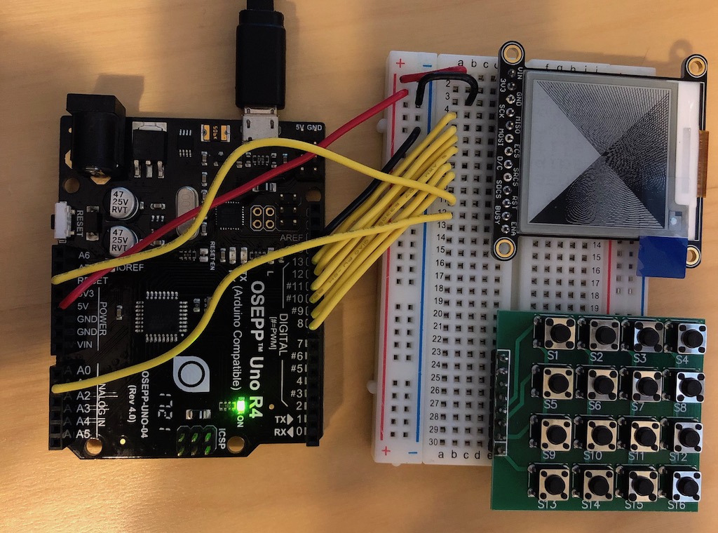
I didn’t have a SIM card yet, so initially I just wired up the button matrix, EPD display, and the Uno to make a minimal “dial a number” routine. After some trial and error I got working. This took up 8 GPIO pins for the button matrix and 8 pins for the EPD. The Uno has 14 dedicated GPIO pins and 6 analog pins. Luckily, you can also use the analog pins for GPIO for a total of 20. I initially used the 0 and 1 (RX and TX) pins for the button matrix, but realized that those are reserved for Serial if you want to have debug printing, so I moved things around a bit to accomodate. A total of 8 (buttons) + 8 (EPD) + 2 (Serial), for 18/20 GPIO pins used.
The first thing I noticed was that the EPD has a very slow refresh rate. About a second and half. I knew it’d be slow, but I assumed it’d be like my Kindle Touch. Slow, but still usable interfaces. Dialing a number is painful because you have to wait until the EPD finishes before pressing the next number each time. It turns out, neither the EPD hardware nor the Adafruit library support partial refresh, so it refreshes and redraws the entire display each time you tell it to display.
Next, I ordered a SIM card from Ting Wireless, a post-pay carrier that charges you only by what you use. I soldered headers to the FONA and wired it up. I realized that the Uno didn’t have enough pins to support everything. The FONA needed a bare minimum of 3. Both the EPD and FONA have a RST pin that should be able to connect to the microcontroller’s RESET pin, and free up GPIO pin, but for whatever reason, I was never able to get that working. An Adafruit support person said I should put a small delay before initializing the peripherals because they might be powering up before the Uno, but that didn’t help. I tried sharing the same GPIO pin for both their RSTs, and voilà! All 20 pins used, but everything was working.
I took the initial work I did on dialing numbers and hooked it into the FONA library to make it actually initiate the call. Miraculously, the calls come through and I can hear the person at the other end. Unfortunately, they can’t hear me. They hear a buzzing, or a scratching as I fiddle with the headphone jack, but not me. Seems like the iPhone headset I’m using is not compatible. I’ve also tried a Bose headset with no luck. I’ll get it figured out, but in the meantime I’m not too worried. I want to add dedicated mic and speaker components anyway.
A little discursion about the software. On an embedded device like this, there’s no OS to speak of, so you’re really writing firmware that directly talks to the hardware. This has some interested consequences that make some things easier than I’m used to, and some things harder. It’s simple because there’s no async, no threading, and things are pretty deterministic. Making it harder is that you don’t get segfaults for accessing memory that isn’t yours. There’re no processes, so you own all the memory. You just accidentally access data that you didn’t mean to. Overflowing memory crashes the device, making it restart.
I represent each “screen” by an object that handles input, interacts with the FONA and updates the EPD display. In OOP-vocab you could call these view controllers, but I’m careful not to be too OOP-y. I have 2KB of RAM, and a clock speed of 16 MHz. In the interest of efficiency, these objects are all allocated at boot and used as singletons. Meticulous state management ensues. Mediating between them is a Navigator object that contains refs to all these singletons and a stack whose head is the currently displayed screen. This design lets me push a view onto the stack, replace the current view in the stack, and pop back to the previous view. It makes it easier to reason about navigation flows. Granted, right now there are only two screens: Dialer and Call. Dialer lets you enter a number and press the dial key, which then pushControllers to the Call screen. When you hang up, it popControllers back to Dialer. replaceController isn’t used yet, but it makes sense later.
So far I’ve been writing everything in the Arduino IDE, and while not my favorite environment, it has served me well.